
42 Wave superposition
Wave superposition, or interference, is the creation of a new displacement shape from two or more waves. Mathematically, the resulting displacement is the sum of the individual sinusoidal components. Excellent animated examples can be found on Dan Russell’s web page Superposition of Waves.
When two waves of the same frequency are present, if their crests are aligned, they are said to constructively interfere and the resulting pattern is a wave of the same frequency with an amplitude that is the sum of their individual amplitudes. On the other hand, if crests align with troughs, then the waves are said to destructively interfere and the resulting wave has an amplitude that is equal to the difference of their individual amplitudes (zero, if the waves have the same amplitude!)
When two waves of slightly different frequency are present, crests and troughs constructively interfere at some locations, and destructively interfere at others. This results in a phenomenon called beating. The frequency of the beating wave can be determined by considering the sum,  of cosine functions of two slightly different frequencies,
  and
and  , here for simplicity allowing them to both have the same amplitude, A.
![\[ \eta(t) = A \hspace{2pt} cos(\omega_1 t)+A \hspace{2pt} cos(\omega_2 t) \]](https://uw.pressbooks.pub/app/uploads/quicklatex/quicklatex.com-cf643704614b7035fcaea5398c79f962_l3.png "Rendered by QuickLaTeX.com")
We will use the following trignometric identity
![\[ cos(a)+cos(b)=2cos\left( \frac{a+b}{2} \right) cos\left( \frac{a-b}{2} \right) \]](https://uw.pressbooks.pub/app/uploads/quicklatex/quicklatex.com-037922fa9eeef32a354386f826c57442_l3.png "Rendered by QuickLaTeX.com")
to change the sum into a product of two waves of different frequencies
![\[ \eta(t)=2Acos\left( \frac{\omega_1 t-\omega_2 t}{2} \right) cos\left( \frac{\omega_1 t+\omega_2 t}{2} \right). \]](https://uw.pressbooks.pub/app/uploads/quicklatex/quicklatex.com-509614933dd55000e4c2d3ff9a7a9095_l3.png "Rendered by QuickLaTeX.com")
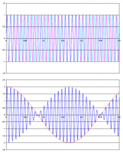
The higher frequency,  , is the average frequency of the two original waves. This wave is sometimes called the “carrier wave”. It is shown by the blue line in the lower panel of the figure.
The second frequency,  , is much lower than the two original frequencies, because the difference between them is small. This wave is sometimes called the “modulation”. It is shown by the red line in the lower panel of the figure.
Media Attributions
- Beat © Barak Sh for Wikimedia is licensed under a Public Domain license
