
4 Section Views
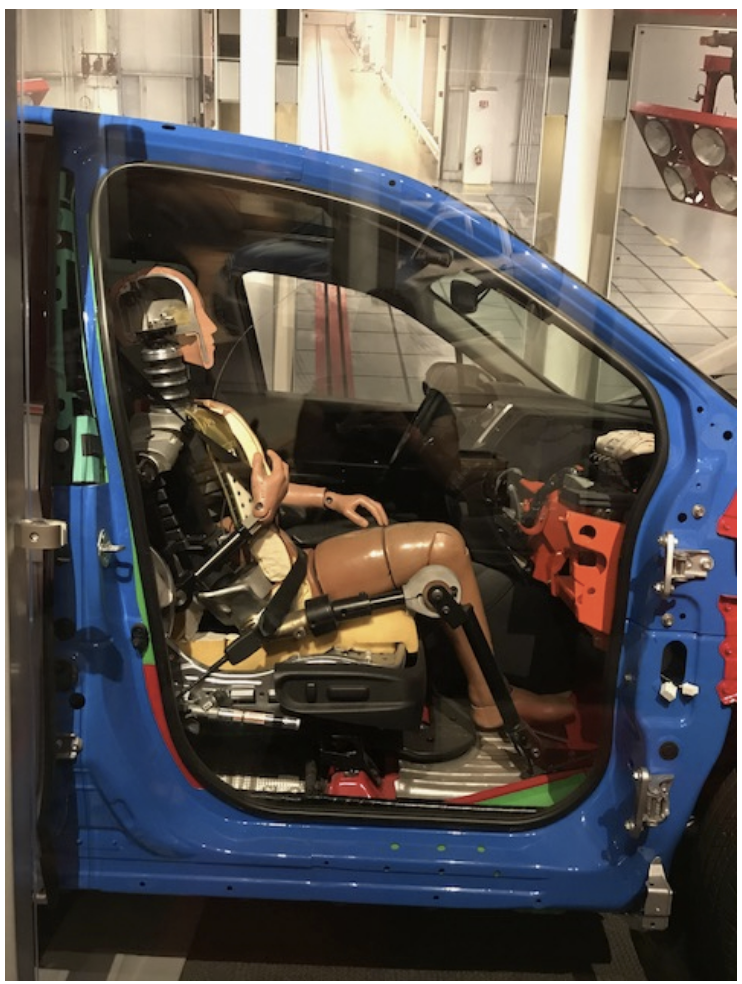
Section views are used extensively to show features of an object or an assembly that are not easily visible from the exterior. This method can be used with both simple and complex objects and involves the use of a cutting plane that dictates what portion of the object you want to remove to reveal a more complex interior. Can you see how part of the crash test dummy is removed so you can see the interior of the design of this complex object in the image below?
While you may be familiar with a full section view that entails splitting an object in half, there are many more types of sections views utilized in technical drawings to clearly describe the design. This section will cover the different types of section views, corresponding technical vocabulary, and help you determine which section view would best communicate important aspects of an object or assembly to others.
 |
 |
Everyday Examples
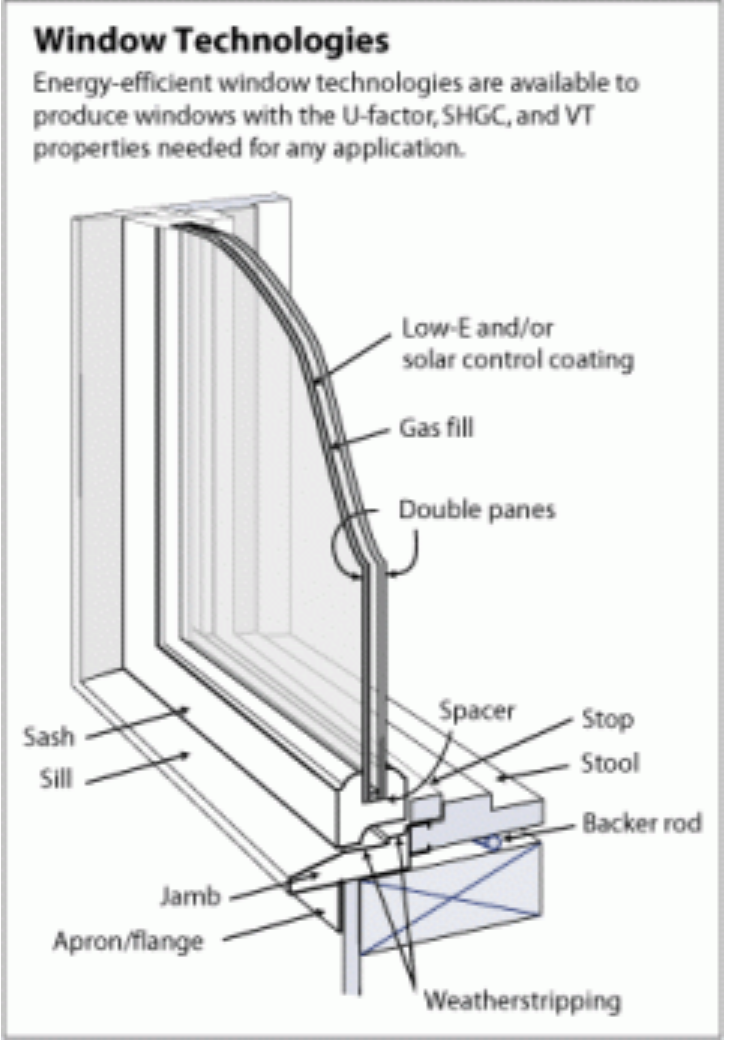
Have you ever visited an automotive dealership, a mattress store, or a window business? Chances are that you encountered a section view in a product advertisement as these views are also often used to show the quality of an object or to highlight differences between product levels or from a competitor. For example, a mattress store may have a broken out section view sample for each different mattress so consumers can see how they are constructed differently and then make a more informed decision if/when they decide to make a purchase. Examine the section view of the window below. This is used to show all the different parts of the window to a potential customer and then the differences in the panes or coatings can be explained in terms of energy efficiency.
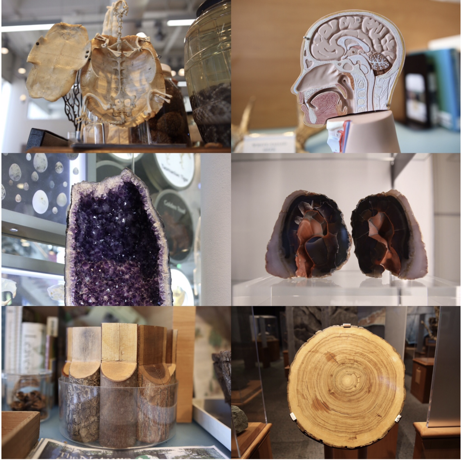
While section views are used extensively in industry and in technical drawing for documentation and communication purposes, they have a very practical application as a teaching tool to show the interior of complex objects in an informal manner. For example, check out these section views spotted at a science museum.
 |
 |
Let’s now talk more about the details of sections views and terminology associated with this topic. In section views we are essentially using a cutting plane to slice an object or an assembly so we can see the part of the interior of the object that we are interested in. The cutting plane changes for different types of section views: it may be straight and go directly through the center of the part, or have multiple bends and kinks to pass through features of interest. You can think of a cutting plane as literally the place where a cutting utensil like a knife or saw is used to slice an object.
Types of section views
Depending on the shape of the cutting plane and the details shown, a section view may be classified as a full, half, offset, aligned, or broken-out section.
Full section
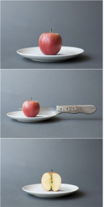
In a full section view, the cutting plane makes a planar cut through the entire part. Most likely if you have any experience in the kitchen, you have observed a full section firsthand when slicing produce in half for various recipes. See the example with the apple below.
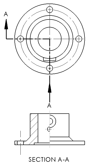
A dashed or “phantom” cutting line on the parent view indicates the location of the cutting plane. The arrows indicate the viewing direction. The section view shows the sectioned part, and is placed according to the standard rules of third-angle projection. Hidden lines are almost never shown on section views.
 |
 |
Half section
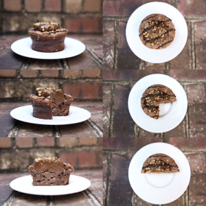
A half section view means that you are only removing a quarter of an object. This type of view is ordinarily used when the object is symmetrical or if you only need to show a portion of a complex assembly. The photo below of a cupcake shows the progression from the whole object to a half section to a full section.
 |
 |
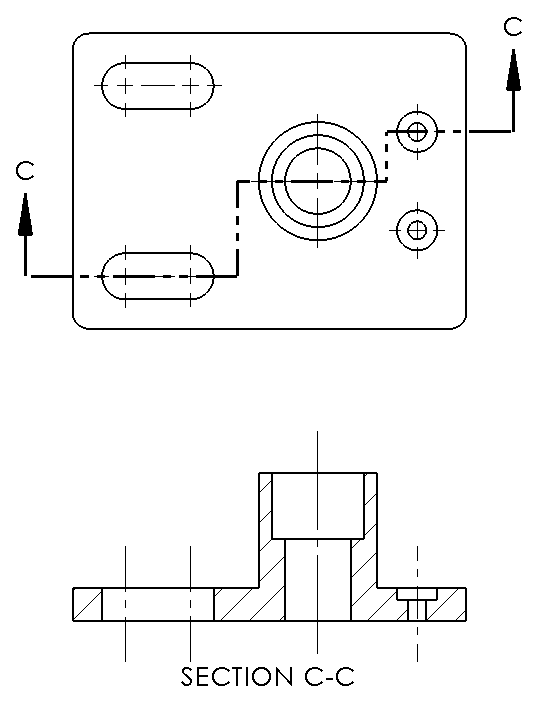
Offset section
Instead of making a straight single cut like in a full section, or two straight cuts (half section), an offset section is a series of straight cuts to reveal interior features of an object. These are more conceptually difficult to imagine but if you were an avid Lego builder you may have seen these when creating larger structures that open to reveal the important aspects of the inside of the structure. The example shows a top and offset section view.
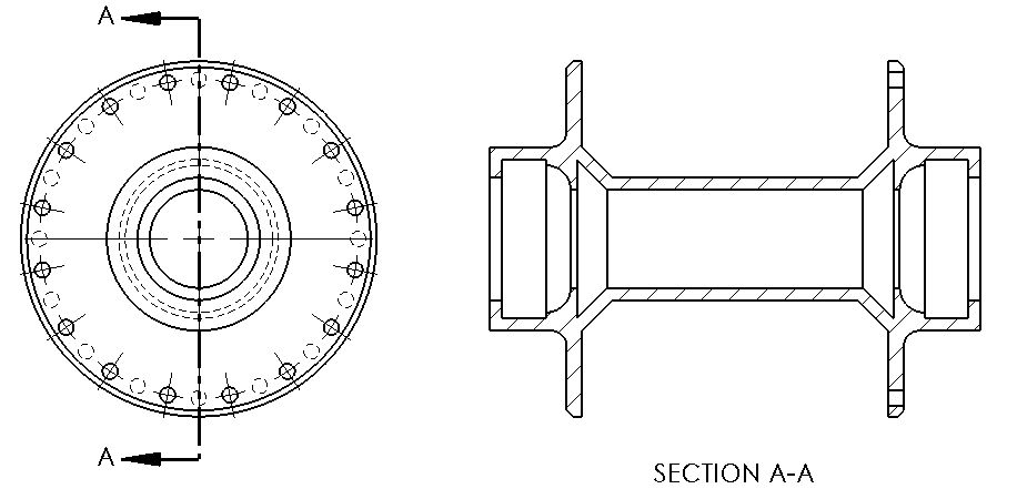
Aligned section
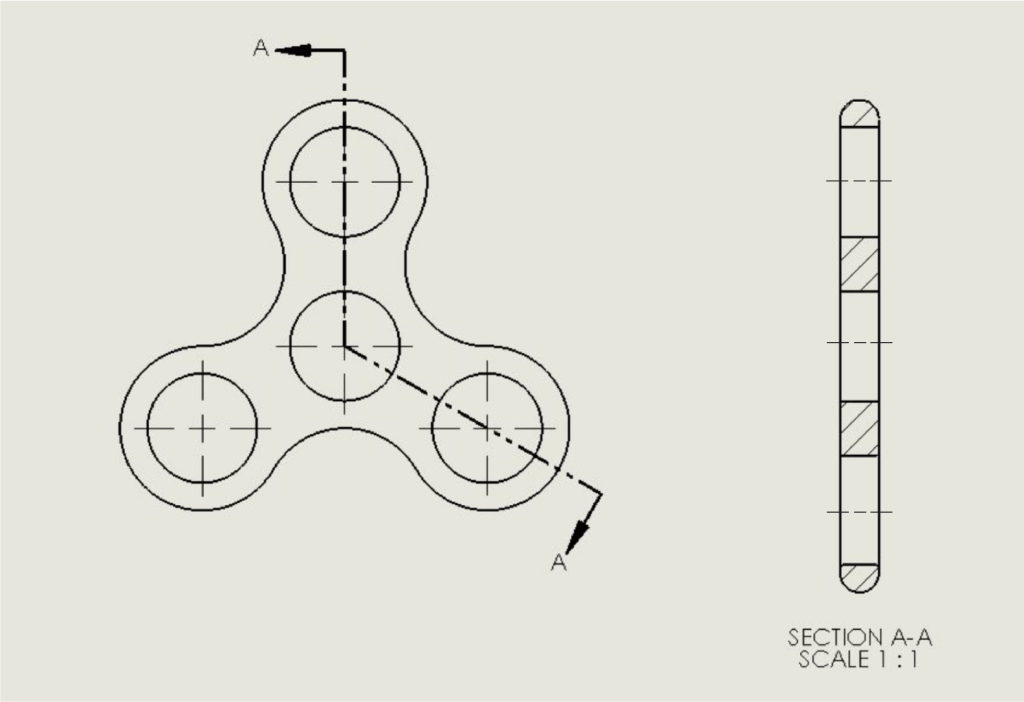
An aligned section view is essentially a special case of an offset sectional view. The cutting plane line is at an angle to show characteristics of non-aligned features. For example, let’s look at the fidget spinner. If we wanted to examine the holes and show that they are equally spaced from each other, we cannot do this with a straight cutting plane (like for a full section) or with a cutting plane bent at 90-degrees (like for a half section). In this case, the cutting plane is bent as seen in the drawing below. The subsequent aligned sectional view shows the symmetry of the holes. Note that this is not a true projection so the sectional view appears taller than the actual object. This type of sectional view is often used with cylindrical objects with one plane of symmetry.
 |
 |
Revolved and Removed sections
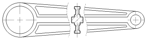
Less common, but still used section views include revolved and removed sections. A revolved section involves showing a section view in-line with the object (like the purple carrot below) and is often used to communicate more complicated cross-sections like you may find in a support beam. Similarly, a removed section involves multiple cutting planes along the length of an object with the removed section views shown adjacent to the object in a manner that is easy to communicate (like the orange carrot below). Removed sections are useful for showing changes along the length of an object such as an airplane or spacecraft.

Examples of engineering drawings using revolved and removed sections are shown below.
 |
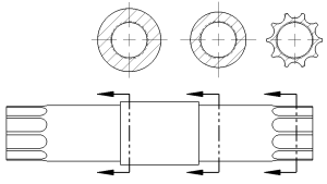 |
| Connecting rod with revolved section. | Bicycle spindle with removed sections. |
Placement and alignment
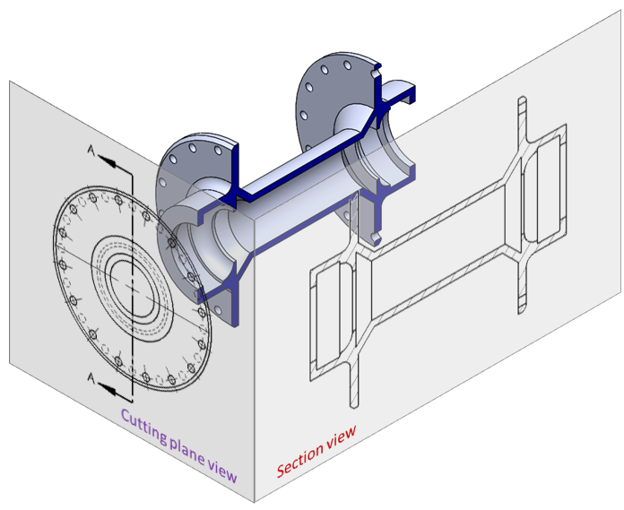
The glass box method described in the chapter on Multiview Layout and Orientation dictates the proper alignment and placement of section views. The cutting plane is indicated by a straight line (this can be a “dashed” line or a “long-short-short-long” line. The arrows at each end of the cutting line indicate the viewing direction for the section view. Note that the arrows point towards the portion of the part that is “kept” after cutting. The viewing arrows are perpendicular to the cutting line. After cutting the model and discarding the half of the part “behind” the arrows, the sectioned part is projected onto the Right view in this example. The the glass box is unfolded to show the cutting plane view and section view in their proper orientations. Note that the viewing arrows always point away from the section view.
There are some occasions where you will break this rule about alignment and placement of the section view. One example was already shown above for Revolved and Removed sections. In the case of a revolved section, the section view is shown directly on top of the parent view. The viewing direction is irrelevant since the section is symmetric about its center line. In the case of a removed section, the section view is shown above or below the cutting line.
In other instances, you might need to put a section view somewhere else on the drawing for space or clarity reasons. If this is the case, make sure that the section view is labeled (e.g. “SECTION A-A”).
Check your understanding
[Classify section views]
Convention used for layout and alignment of multiviews in the U.S., Canada, Australia, and Japan. The right view is placed to the right of the front view, and the top view is placed above the front view.
