
3 Auxiliary Views
An auxiliary view is used to show the true size and shape of an inclined or oblique surface that can not be otherwise seen from any of the six principal views discussed in the previous chapter. You can think of an auxiliary view as a specialty view that is sometimes necessary for design clarity or dimensioning purposes for a non-normal surface. While this technique is used less often than detail and section views, it is frequently used for parts which have critical features or dimensions or inclined planes.
Inclined Surfaces
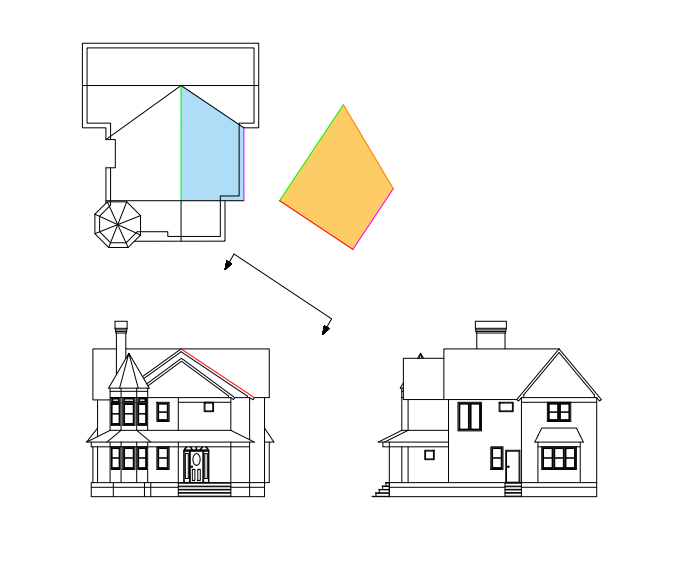
An inclined surface is perpendicular to one principal plane, but makes some angle between 0 and 90 degrees with the other two. The example below shows an auxiliary view of a roof section (it’s actually a partial auxiliary view, since the rest of the house is not shown). The blue section of the roof in the top view is foreshortened (squished along one axis), and therefore appears smaller than it really is. It is shown in true shape and size in the orange auxiliary view. The edge marked in green is the same edge in the top view and auxiliary view. You will see later why creating an auxiliary view from a view in which a surface appears in edge view guarantees that the surface will be shown in true size and shape in the auxiliary view.
The Fold Line Method
While auxiliary views can be easily created in any CAD software, the main methodology for creating an auxiliary view manually is the fold-line method. We won’t go into a lot of detail here for constructing an auxiliary view by hand, but it is important for you to understand how an auxiliary view relates to the other principal views and be able to identify an auxiliary view in a technical drawing.
Recall the glass box model that we used for orthographic projection and construction of multiview drawings of objects. Remember how we could essentially “unfold” the box to get the six principal views? The fold-line method builds on this example by adding in an extra panel that shows the auxiliary view that shows the inclined surface in true size and shape.
Begin by identifying the view in which the inclined surface appears as an edge (in this example, it’s the front view). Then add a new fold line parallel to this edge. Add a new imaginary panel to your glass box which is hinged along this fold line. Create your orthographic projection on this new panel, and then unfold the glass box to yield the complete multiview drawing.
In actual practice, you will be creating auxiliary views automatically using CAD software. On actual drawings, your views don’t need to be spaced out so that the imaginary glass box could be folded up again. You can move them closer together or further apart as necessary for organization and clarity.
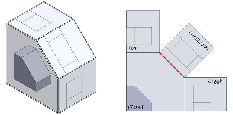
Look at the example below. The blue face is inclined: it appears in edge view in the Front view, but is foreshortened in the Top view). The inclined face appears in true shape and size only in the auxiliary view. In this case, the fold line and viewing direction is shown explicitly, but this is not always required. The angle of the fold line may be inferred by the placement and alignment of the view.
Although the auxiliary view clarifies the geometry of the inclined face, it actually distorts everything else. The circular bosses are compressed to ovals and the lip at the base of the part appears shorter than it really is. In this case, you may choose to create a partial auxiliary view by cropping out the parts you don’t want to show. This can be done on any type of view including a principal view or a section view. The cropped edge is often indicated by an irregular or jagged line, but this is not necessary, as demonstrated on the house drawing above.
When is an auxiliary view needed?
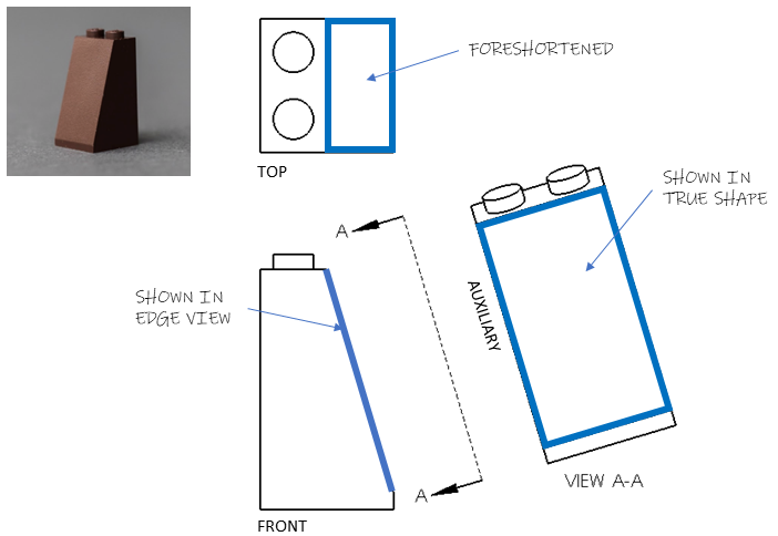
The existence of an inclined face doesn’t necessarily mean you need an auxiliary view. The LEGO brick above could be completely defined by only the front and top views. An auxiliary view is only needed when there are important dimensions or features on the inclined face which need to be shown in true shape.
Check your understanding
Oblique Surfaces
An oblique surface is one which is not parallel or perpendicular to any principal view. An oblique surface always appears foreshortened (distorted) along both directions in any principal view. Bringing an oblique surface into true shape requires two steps: a primary auxiliary view and a secondary auxiliary view. The primary auxiliary view brings the oblique surface into edge view. Then the secondary auxiliary view brings the oblique surface into true shape using a fold line parallel to the edge view of the surface.
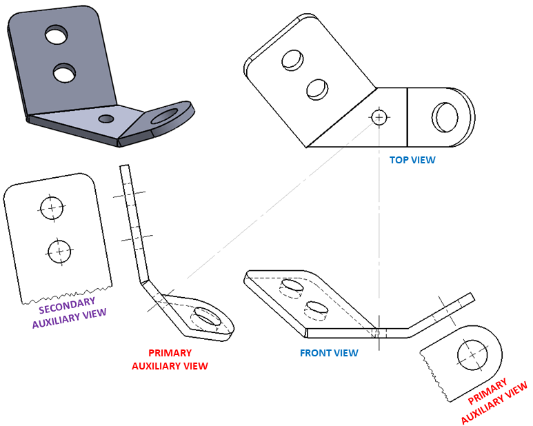
The tab with two holes on the sheet metal bracket shown above is an oblique face. Note that it appears foreshortened in both the top and front views. The primary auxiliary view on the left is projected from the top view, bringing the oblique surface into edge view. The secondary auxiliary view is then projected from the primary auxiliary view, bringing the surface into true shape. The fold lines are not shown.
The tab with a single hole is an inclined face because it appears as an edge in the front view, but appears foreshortened in the top view. This face only requires one auxiliary view, projected from the front view, to bring it into true size and shape.
