
1 Orthographic Projection
Engineering components are 3-dimensional, but the tools that we use to communicate about them—documents and computer screens—are 2-dimensional. It is necessary to reduce the 3D object to a 2D representation while still communicating all the essential details needed to understand and manufacture the component. For engineering applications, the orthographic projection is the tool of choice in most cases.
Creating an orthographic projection
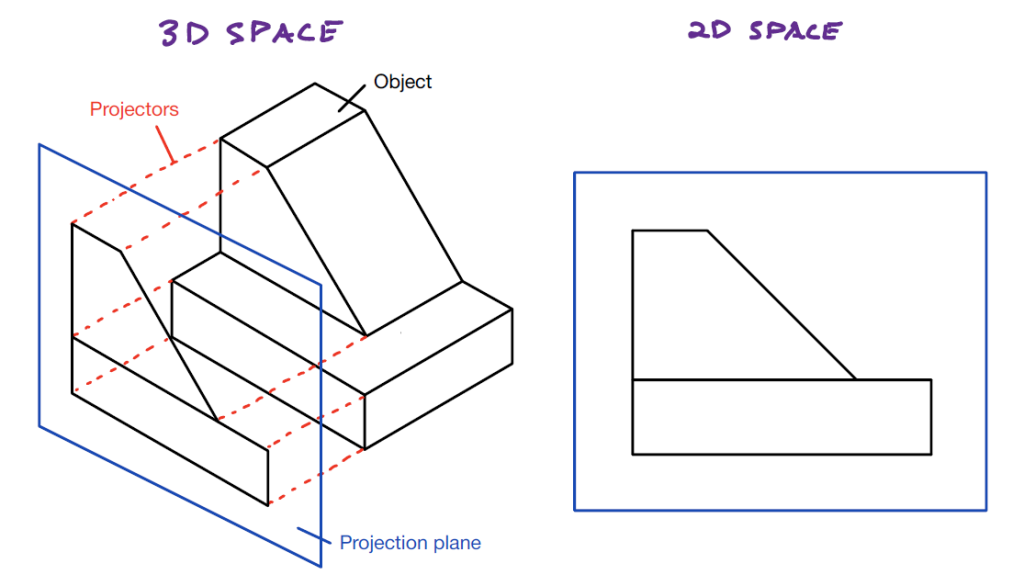
Mathematically, an orthographic projection is created by defining a flat projection plane, and then projecting the features of the 3D object onto the plane along lines (or projectors) which are perpendicular to the plane. The image which results is similar to what you would see if you held the object far away from you and viewed it along the direction of the projectors. Any dimensions or features of the object which are parallel to the projection plane will be shown in true size and shape (not distorted). Any features lying on planes not parallel to the projection plane will be distorted along one or both axes. In the most extreme case, a plane on the object which is perpendicular to the projection plane will appear as a line on the orthographic projection.
Display style
Orthographic projections are not shaded or hatched. The projection only shows edges and boundaries. Visible edges or boundaries (including the extent of curved surfaces) are shown as solid lines. Edges or boundaries which are obscured (not visible from the chosen viewing direction) are shown with dashed lines. The center lines of holes or solid cylindrical features are indicated with a special “long-short-long” line which extends slightly beyond the ends of the feature. In this way, an engineering drawing can actually show more information than a photograph taken in the same orientation.
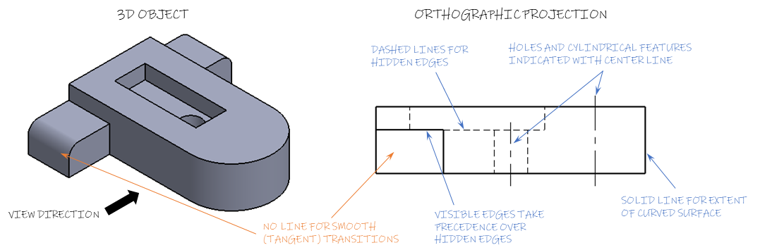
The example above shows several examples of line style. The boundary between the flat front face of the tab on the left side of the part and the rounded face is called a “tangent edge.” Tangent edges are generally not shown on orthographic projections.
When multiple edges project to the same line on the drawing, the line type is determined by the following precedence: (1) visible lines, (2) hidden lines, (3) center lines. In the example above, a visible edge and hidden edge both project to the same line, so a solid line is shown. Similarly, if a center line was overlapped by a hidden line, only the hidden line should be shown.
Your CAD software (e.g. SolidWorks) will not always correctly enforce line precedence, so you must exercise your judgement to make the drawing clear and correct. Additionally, many of the rules about when lines should or should not be shown can be broken if doing so makes the drawing clearer and easier to interpret.
