
2 Multiview Layout and Orientation
A single orthographic projection almost never provides enough information to fully describe a component. This is because all of the information about dimensions parallel to the viewing direction are lost completely. A multiview drawing combines several orthographic projections into a single document, often including a pictorial representation like the photo shown below in the top right. By comparing multiple views, one can reconstruct the original 3D object.
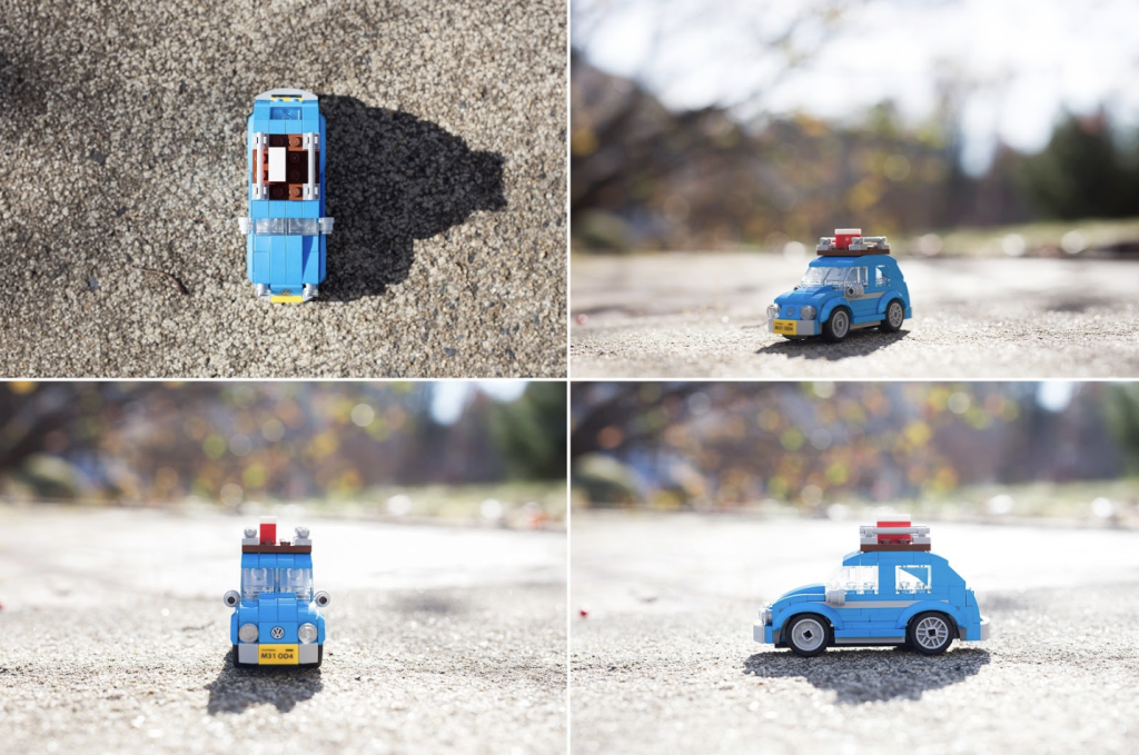
Adjacent views are related by a 90-degree rotation around the fold line separating the two views. A multiview drawing usually consists of three views: a Front view, a Top or Bottom view, and a Left or Right view. Although in theory the part could be placed in any orientation, the views are usually chosen to coincide with a natural symmetry of the part—for example, the front, right, and top of the car shown above. These are called the principal views.
Placement and Alignment of Views
The views in a multiview drawing are placed with respect to one another according to a specific convention. In the United States, Canada, Japan, and Australia, the third-angle projection convention is used. Proper alignment and placement may be obtained by the following procedure: imagine that the part is enclosed inside a glass box. Project the part onto each of the panels of the glass box using orthographic projection. Finally, unfold the panels of the glass box. Using this rule, the right view is placed to the right of the front view, and the top view is placed above the front view. This might seem like the only intuitive placement, but the rest of the world actually uses the first-angle projection convention, where the right view is placed to the left of the front view, etc.
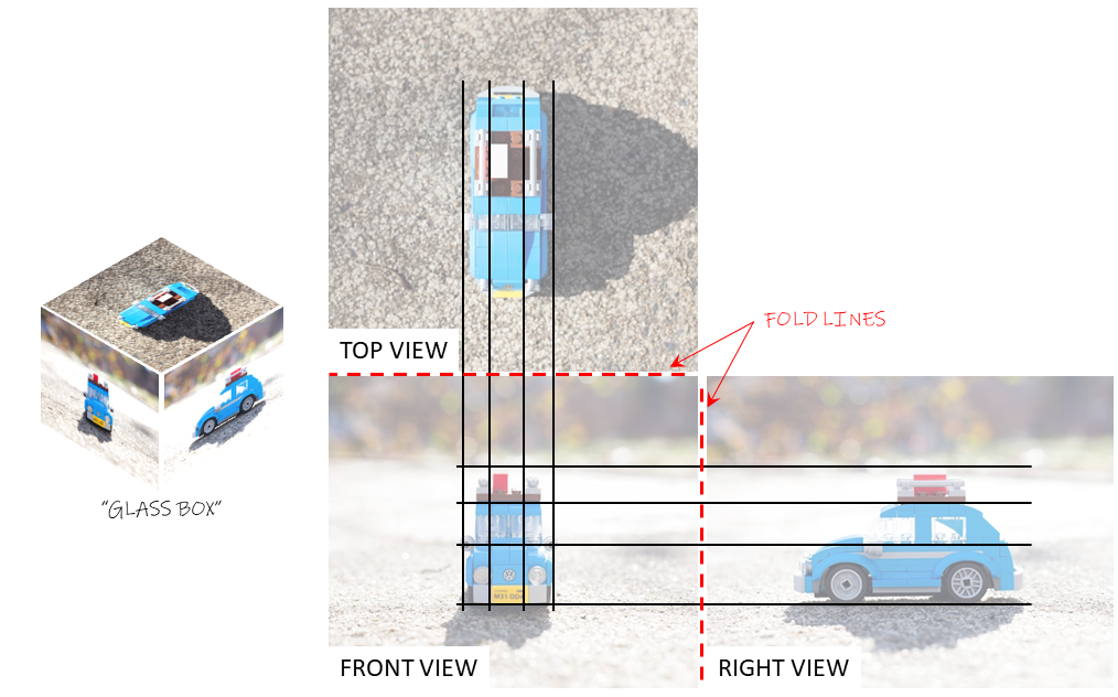
The glass box method also ensures correct alignment of views. The same feature shown in two adjacent views must lie on a line perpendicular to the fold line. Notice that the side-view mirror on the car above appears at the same vertical position in both the front and right views, while the wheels appear at the same horizontal position in the front and top views.
The right and top views also share a common axis along the length of the car. The same feature in these two views will appear the same distance away from the fold line. This fact is useful when constructing your own multiview projections by hand and correlating features between views, but fold lines are not shown in usual engineering practice, so there is no specific convention dictating the spacing between adjacent views.
Choosing Appropriate Views
You don’t always need three unique views to completely describe an object. Sometimes you need more, and those additional views might be of a special kind like a section view, auxiliary view, or detail view. Sometimes you only need two, particularly if the part is symmetric about a plane or axis.
You should start by selecting the most descriptive view of the object. You will generally choose this as your front view, and then construct additional views from it as necessary to fully define the object. Each view will give different information and will be best-suited to answering specific questions about the object.
Activity
Find an object nearby that can be held in one hand. After examining it, identify what you think would be the best front view (most descriptive). While looking at the front view, rotate the object towards you to examine the top view. Now, rotate the object back to the front view. To look at the right side view, turn the right side of the object towards you.
We will demonstrate this with a child’s tiger toy and a porcelain crane.
 |
 |
The details of the tiger’s face are most visible in the front view, but the right view gives a better perspective on its legs. The approximate surface area of the crane’s wings are best seen in the top view, which shows their width and length, but the curvature is only visible in the front view.
Check your understanding
Activity: Create a multiview drawing
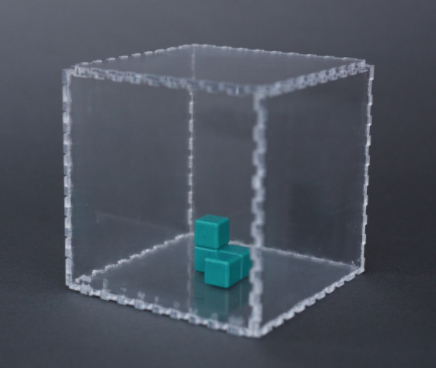
Let’s make a multiview drawing based on the object in the glass box. Get a sheet of rectangular grid paper and we will step through the process to make a multiview drawing together. You can assume that the object is composed of equal-sized perfect cubes (ignore the seams between them). Use the plane of the box closest to the camera as the front view.
Imaginary line between two adjacent orthographic projections indicating the "fold" in the glass box representation.
Convention used for layout and alignment of multiviews in the U.S., Canada, Australia, and Japan. The right view is placed to the right of the front view, and the top view is placed above the front view.
Convention used for layout and alignment of multiviews in most of the world except the U.S. and a few other countries. The right view is placed to the left of the front view, and the top view is placed below the front view.
Two orthographic projections whose viewing directions are 90 degrees apart from one another. Adjacent views share a common coordinate axis.
Orthographic projection showing the inside of an object by "cutting" it open with a flat plane. Any material touching the cutting plane is shown as hatched areas. Hidden lines are generally not shown on section views.
Orthographic projection which is not one of the principal views (XY, XZ, or YZ plane).
Orthographic projection showing a portion of a part enlarged to show more detail. A detail view almost always accompanies another view on which the region to be enlarged is marked.
