7 Dimensioning Standards
While you may not be accustomed to reading dimensions from a technical drawing, you probably have had practice using dimensioning principles in your everyday life. For example, if you were looking at apartment or house plans, you may look at the room dimensions to see if the space would fit your furniture. Conversely, if you are looking to purchase a new couch, you may measure the couch first to see if it will fit in the space where you want to place it. Often dimensions on a technical drawing are a smaller scale (inch or millimeter), but the idea of using this information to communicate size and location ideas is more familiar than you may have initially realized.
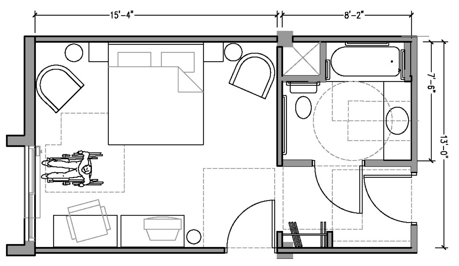
Here is an example of a hotel room layout that is compliant with the American Disabilities Act. In this case, the overall room dimensions are given as these are the minimum dimensions needed to fit generic hotel furniture while leaving the proper space for wheelchair mobility. Note that only dimensions lying in the horizontal plane are shown. You couldn’t, for example, indicate the height of the bathroom counter this way without including another view.
Dimension standards and placement
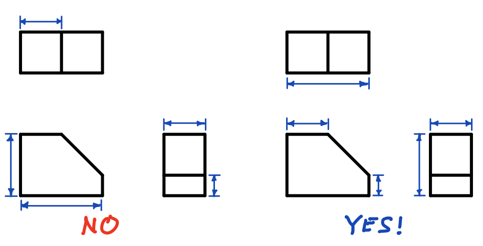
The general guideline is that each dimension should be placed on the view which shows the dimensioned feature most clearly, and which gives the clearest and least cluttered drawing. On a multiview drawing, dimensions should generally be placed between adjacent views. Dimensions should be placed strategically to avoid crossing extension lines, unless doing so would clutter the drawing or move the dimension too far away from the feature being dimensioned.
Extension lines are used to connect the dimension line to the visible edges of the feature being dimensioned. You should not dimension to hidden lines: use a section view to make hidden lines visible, or use a hole callout if possible.
Size dimensions
Size dimensions indicate the size of basic shapes like arcs, prisms, cylinders, and holes.
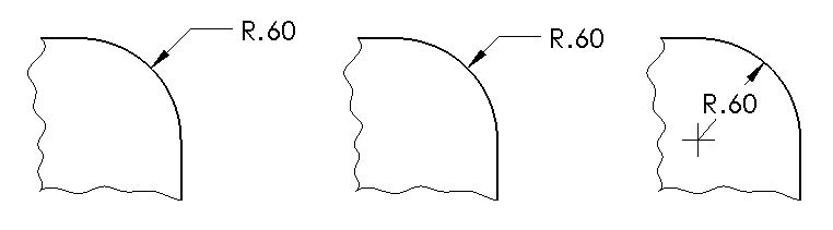
A circular arc is dimensioned by its radius using the symbol “R”. The arrow and leader should be placed to avoid clutter and overlaps.
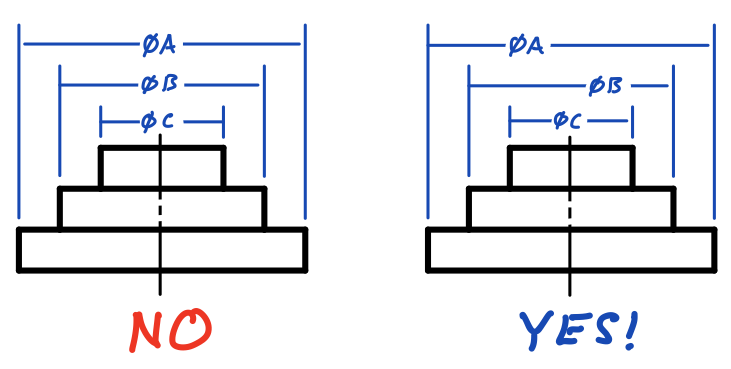
A cylinder is dimensioned in side view using linear dimensions for both the length and diameter. A diameter symbol is used on the diameter dimension. When dimensioning a part with multiple concentric cylindrical features, you should stagger the dimension numbers so that they are easier to distinguish.
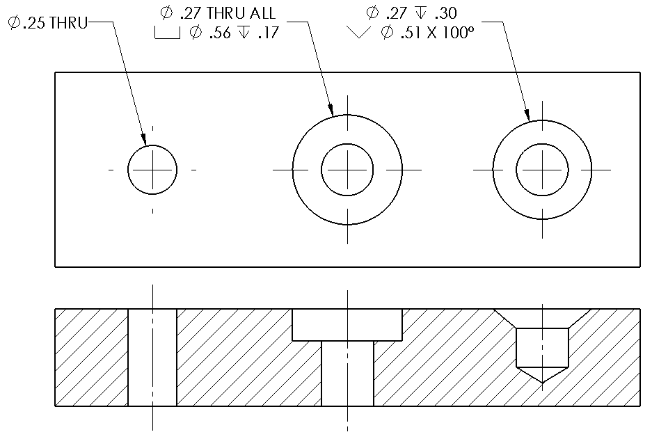
A hole is dimensioned using a callout in the view in which the cross-section appears as a circle. If the hole has a countersink or counterbore, this information can also be given in the hole callout.
Angular dimensions
[Section in progress]
Location dimensions
[Section in progress]
Baseline vs. chain dimensioning
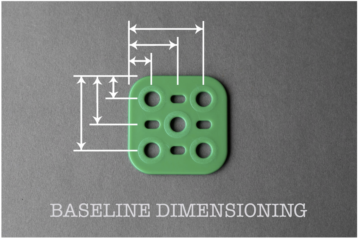
The part below is from a children’s toy set and is meant to be attached to other parts using standard plastic nuts and bolts. For a toy like this to work as intended, the parts need to be created in a manner so that they are interchangeable. Here is a simple base plate that we will use to examine the two main dimensioning placement methods. What is more important in this case: the position of the holes relative to the edge of the plate or the position of the holes relative to each other?
If the position of the holes relative to the edge of the plate is important, we would use baseline dimensioning. The relative location of all of the holes would be made to the most important edge.
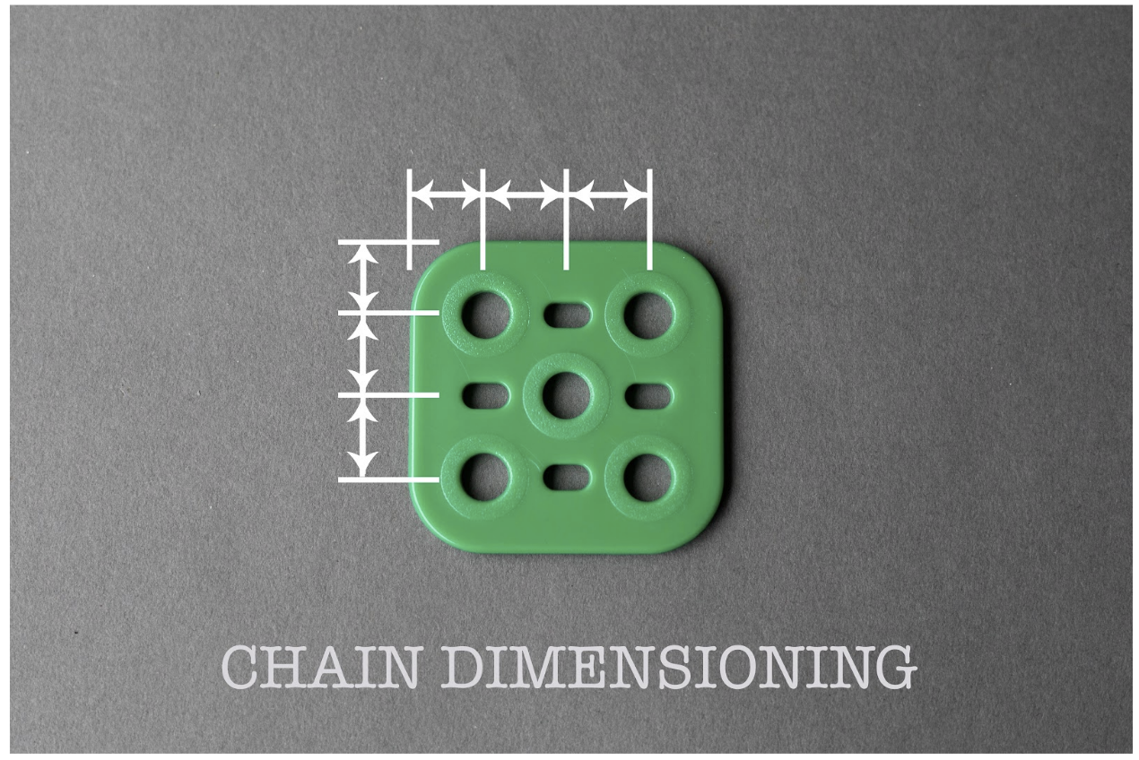
Now, let’s consider if the position of the holes relative to each other is important. In this instance we would use chain dimensioning. The dimensions between each hole would be given in this dimensioning placement method.
 |
 |
Mathematically, baseline and chain dimensioning are equivalent. What separates the methodologies is the design intent. If the distance to an edge is the most important design consideration, then use baseline dimensioning. If the distance between the features of the design is the most important for interchangeability, then use chain dimensioning. You will revisit this problem again in the chapter on tolerances and consider the implications of these two dimensioning schemes when considering imperfections in the manufactured part.
Units
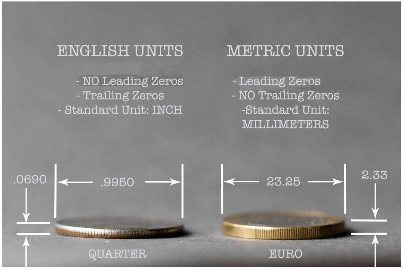
While many students in the United States are accustomed to using the English unit system, many international companies use Metric units. To help distinguish between the two measurement systems, standards have been developed regarding how to display the numeric value of the dimension. Let’s look at the measurement of an American Quarter (in English units) compared to a European Euro (in Metric units).
 |
 |
The number of decimal places depends on the desired precision of the part. It is customary to include two decimal places unless additional precision is required.
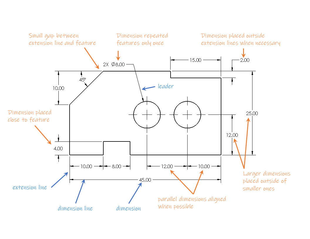
Dimensioning quick reference
CAD Software like SolidWorks will automatically format dimensions, arrows, and extension lines according to the selected standard, but you will still need to do a lot of manual work to present your dimensions correctly and clearly. The example below illustrates definitions and guidelines: