
15a. Assembly of the Dual-Control Cable System
Component Parts of the Dual-Control Cable
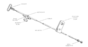
The dual-control cable consists of the cable, split-housing, hanger, retainer, baseplate and rubber disc, leather lift tab, and ball terminal. The control system may be constructed with standard or heavy-duty parts. This cable is interchangeably called a split-cable housing or dual-control cable or fair-lead cable.
- The dual-control cable has two lengths of housing positioned above and below the elbow axis.
- This cable housing is a guide or channel for the transmission of force by the cable. The split housing allows for two separate functions: TD operation and Elbow flexion.
|
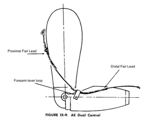
- The two lengths of housing are attached to the prosthesis via two fairleads: the baseplate/retainer and the forearm lever loop. The fairleads act as “reaction points” as the cable bends through the housing.
- The location of the fairleads (reaction points) affects the required force and excursion to operate the prosthesis.
Forearm lift tab location
|
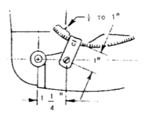 |
Base Plate and retainer
To find the placement: Draw two vertical lines: one on the lateral side through the elbow axis and one on the posterior side of the socket. Draw the midline. |
 |
Process to Assemble the Dual-Control Cable
- Attach the ball terminal to the cable and to the terminal device.
- Assemble the hook to cable adaptor, if necessary.
- Slide the housing over the cable. If adding a nylon liner, cut the nylon liner ½” longer than the housing and flare the ends with a heated flaring tool. Or the liner may be cut to the same length and held in place with ferrules. Be sure to file the housing ends to remove projecting end of cut wire.
- Screw retainer over the housing and align retainer with the baseplate. Check opening of the TD while in neutral pronation/supination or while the thumb of the TD is closely aligned to the baseplate.
- Attach the forearm lift tab.
- Adjust distal housing to allow a 3 mm gap between the housing and the base of the ball terminal while the TD is open.
-
- At its proximal end, it should extend ½” beyond the forearm lift tab.
- At its distal end, it should be about 2-3mm from the triple swivel when the TD is fully opened and aligned so that the cable is running the shortest distance to the lift tab and the elbow is fully flexed.
- Rivet the lift tab to securely hold the housing.
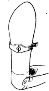
- Attach the baseplate to the humeral section (see instructions for two baseplates below).
- Screw the retainer onto the proximal housing.
- Adjust the proximal housing on the cable to allow full elbow flexion and extension. The housing, the lift tab and the retainer should position the cable to run anterior to the elbow joint axis.
-
- At the distal end, it should be about 2-3mm from the distal housing at full elbow flexion.
- At the proximal end, the length of housing should extend ½” beyond the retainer to avoid sharp bends as the cable exits the housing. Assess with the TD closed, fully pronated and the elbow extended.
- Attach the hanger close to the proximal end of housing when elbow extended and VO TD closed and pronated. It should never hit the proximal end of the proximal housing.
- Check control cable efficiency.
Optional: Two baseplate setup for split cable design
The two retainers and baseplates (for short TH) may be used to attain improved efficiency in force over the single baseplate and retainer position. The goal is to position the path of the cable as far anterior to the elbow joint axis (to ease elbow flexion) and the control attachment strap as low on the scapula as possible (to capture as much excursion as possible).
- The proximal baseplate sets the location for the control strap
- The distal baseplate sets the location of the cable relative to the elbow joint axis
- Mark lateral and posterior reference lines.
- With elbow extended, pull the cable in a straight line from the forearm lift tab keeping it 1” anterior to elbow axis. Mark intersection with lateral reference line. Temporarily mount the base plate. Pull cable to check ease of forearm flexion.
- Next pull the cable in a straight line towards the direction of C7. Mark the intersection with the posterior reference line. Temporarily mount the proximal base plate.
- Alleviate sharp curves in the cable to reduce friction.