6b. Assembly of the Bowden Control Cable
Purpose of Bowden Cable
The Bowden cable is a single control system, it operates one component.
In the transradial prosthesis, the Bowden cable operates the TD. The linear movement of the inner cable transmits a pull force. Other applications include clutch cables, throttle cables, brake cable, valve control cable, handbrake cable, bicycle brake cable. In each application, the cable has one purpose.
Single Control System: Bowden Control
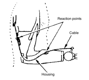
Bowden control consists of a continuous length of stainless-steel flexible housing, with a retainer at each end, through which the control cable slides. The retainers on the housing fasten it to the prosthesis and serve as reaction points when force is applied to the cable. The Bowden cable can be shaped to follow a straight or curved path with intermediate retainers, and can be moved through various angles and curves while being operated, without these movements affecting the over-all length relationship between the operating ends of the cable.
A typical Bowden cable control system is shown with a transradial single control system. The Bowden is also used on the transhumeral Triple control system and may be used in conjunction with a linear transducer to operate an electrically powered component.
 |
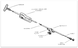 |
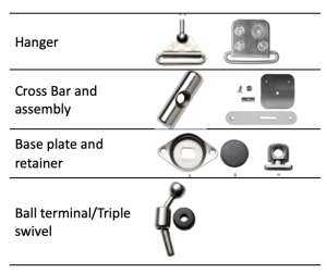
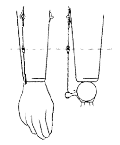
The control system assembly for a transradial body powered prosthesis consists of the cable, housing, housing cover, ferrules, hanger, retainer, baseplate and rubber disc, crossbar, crossbar assembly and ball terminal. The control system may be constructed with standard or heavy-duty parts.
The instructions below describe two processes: 1) assembly of the Bowden cable and 2) control system bench test.
Process to Assemble the Bowden Cable
1) Gather supplies and consider how all components will fit together, e.g., check how cable length may differ if using two different types of TDs.
|
2) Attach the ball terminal to the cable and to the terminal device.
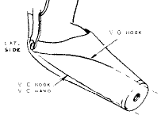
Hook to cable adaptor: When using both a hook and a hand, notice that the location of the attachment for the ball terminal may be longer or shorter. The difference in length requires a hook-to-cable adaptor.
|
3) Attach the baseplate to socket with rubber disc in place.
|
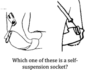 4) Attach the crossbar assembly to the cuff. 4) Attach the crossbar assembly to the cuff.
|
5) Set up the housing
|
| 6) Slide the housing over the cable.
|
7) Check the locations of the retainer, crossbar, and overall length of the housing.
|
Bench Test the Control System
Do this BEFORE the patient comes in for fitting.
- Check the housing length and position:
- Full operation of TD in pronation and supination
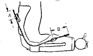
- No stretching of the housing when the elbow is in full extension between baseplate and crossbar
- 2.5cm of housing proximal to the crossbar to prevent strain
- NO sharp bends
- Check the cable:
- Long enough to allow full ROM of pronation and supination without activating the TD
- Fittings crimped or soldered without concentrating bending forces at transition
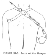
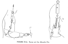
- Measure the control system efficiency: The efficiency of a control system is influenced by the friction between the cable and its housing. This efficiency refers to the system’s ability to transmit the same amount of force at the output as is applied at the input.
- Control system efficiency = Force at TD/Force at harness
-
- The control system efficiency should be 80% or greater for the single control harness
-
- Force applied at TD =
- Force applied at Harness =
- Control system efficiency = Force at TD/Force at harness
 |
 |
Historical Knowledge
Biceps Cineplasty is a surgical procedure performed in the 1940s and 50s intended to allow operation of the prosthesis without a cable. The biceps muscle was divided: one belly continued to flex the elbow as normal while the other muscle belly was used to pull on the cable. To do this, a skin tunnel was constructed from the 2nd belly and a transverse rod was placed through the skin tunnel. This 2nd muscle belly no longer acted on the skeleton. This operation is no longer performed because the training to operate two different muscle bellies was too complicated to learn and the introduction of myoelectric control provided a more useful method to operate the prosthesis without a harness.
The image below illustrates the bench test for someone who has a biceps cineplasty.

 possible