6c. Assembly the Figure-8 Harness
Purpose of Figure-8 Harness
- Suspension: through the inverted-y strap
- Excursion: through the control strap
Parts of the transradial body powered figure-8 harness
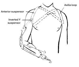
- Axillary loop
- Captures the motion of the scapula through the soft tissue.
- Control attachment strap
- Originates at the cross point, passes over the distal 1/3 of the scapula to the metal hanger on the control cable, then looped back through a 4-bar buckle for adjustability (largest space goes toward the ring)
- Direct pull on the cable for control operation
- Hanger should not be on scapula.
- Anterior Suspension Strap
- Prevents distal migration, suspension of the prosthesis!
- Originates at the cross point, passes over the affected shoulder and the deltopectoral groove.
- Attaches to the buckles at the anterior proximal portion of the triceps pad in the form of an inverted “Y”.
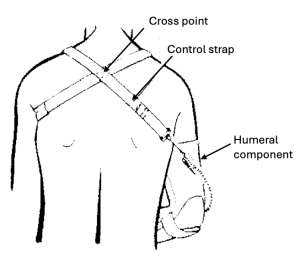 Humeral component
- Force transmission to the harness from the socket with a flexible triceps pad
- Force transmission to the harness from the humeral cuff if full cuff
- Location of the crossbar assembly varies on the length of the lever arm and arc of cable travel.
- Prevents cable from hitting arm and transmits force.
- Crosspoint
- Optimal position is about 1” (2.5cm) below C7 and 1” (2.5cm) toward the contralateral side on the back.
- Tradeoffs
- Toward contralateral side: less comfort in axilla for pt and smaller work envelop, but can capture more excursion
- Toward ipsilateral side: more comfort in axilla for pt, but less excursion
- Crossback strap (optional)
- Placed between the control attachment straps of the bilateral harness or the axilla loop and the control attachment strap of a unilateral harness system.
- Tradeoffs
- Pro: increase efficiency of the harness to capture excursion because it prevents the harness from rising up the back.
- Con: harder to don the prosthesis
Process to Assemble the Figure-8 Harness
1) Gather supplies:
- ½” webbing, for inverted-y
- 1” webbing, for anterior suspensor, axilla loop, and control strap
- ½” flat buckles, for proximal end of humeral cuff or triceps pad
- Plush (TRS) padding or vinyl tubing, for axilla
- 1” four-bar buckles, to allow adjustability
- yates clamps, to hold the straps in position before sewing
| 2) Inverted-Y:
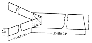
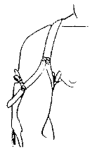
Sew two 12-inch pieces of ½-inch webbing to the 1 inch webbing as illustrated to the right. Sew this with a box and cross pattern of stitches through the materials. Burn small holes through the lower third of the ½-inch webbing with a thin wire and fasten this through the buckles to the top of the triceps pad or humeral cuff.
|
|
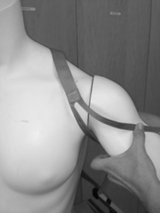
| 3) Lay the 1″ webbing along the deltopectoral groove.
The inverted-y and anterior strap provide suspension. With the patient, when evaluating the axial load, observe the tension in this strap. Ensure that it remains in the deltopectoral groove and is comfortable. |
 |
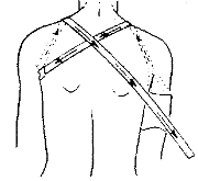
| 4) Continue placing the strap over the ipsilateral shoulder, diagonally across the back, under the opposite axilla, over that shoulder and across the back.
The loop around the contralateral shoulder is called the axillary loop. The point where they cross is the crosspoint. The “book” location for the crosspoint is 1 inch below C-7 and 1 inch toward the contralateral side. |
 |
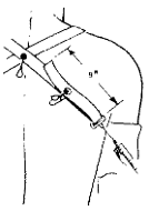
| 5) From the cross point, the control strap extends over the lower third of the ipsilateral scapula.
6) Thread the 1″ webbing through the hanger. |
 |
| 7) Cut a piece of vinyl tubing or the TRS padding so that it is long enough to extend two inches beyond the front and back edges of the axilla. |
8) Complete the harness
-
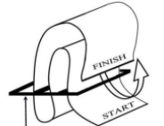
- Sew the crosspoint with box and cross pattern or use the NW ring or BAHA ring.
- Sew 4-bar buckles (largest space goes toward the ring)
- you may use as many buckles as necessary, but likely need to use at least one for the control attachment strap
- Add padding (e.g., neo-axilla padding) to axilla region for comfort.
 |
 |
 |
9) On the patient, check the comfort and operation of the harness.
Have the patient don the prosthesis and hang their arm in a relaxed position. Assess the location of the straps.
- All straps should be comfortable and taut without twists or kinks.
- Location of cross point: 1 inch (2.5cm) below C7 and towards sound side
- Control attachment strap: passes over the lower 1/3 of scapula
- The intersection of the ‘Y’ should be positioned about 2.5cm superior to the tendons (2.5cm distal to clavicle).
- Evaluate suspension. While placing an axial load on the prosthesis observe the tension in the anterior suspensor and inverted-y strap. Ensure that it remains in the deltopectoral groove and is comfortable.
- Under loading the inverted-y will be located at the lowest portion of the pectoralis tendon.
- The hanger should be positioned so that it is either “always on the back or always off the back”. If the hanger is positioned so that it moves from the air and then onto the patient’s back, the skin may bunch up and be pinched.
- By positioning the hanger always off the back, there is less chance that the hanger will catch or drag across the skin.
- By positioning the hanger always on the back, the patient won’t get pinched as the hanger moves on their skin. However, if the hanger is always on the back, the housing should never contact their skin because the skin may be pulled into the housing as the cable travels in and out of the housing.
Ask the patient to perform TD operation in various locations to assess the position of the harness across the back.
Ask the patient to perform some lightweight functions moving the arm and shoulder through various ranges of motion as you assess the position of the straps across the back.
- Adjust the buckles and the harness to assure that there is less than 1 inch of displacement of the socket on the residual limb as the patient lifts heavy objects, the control strap is comfortable in the patient’s axilla and across the back, and the axilla loop is as comfortable as possible.

