6d. Transradial Harnessing Variations
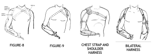
The type of harness depends on the control and suspension needs for the patient.[1]
Figure 9 Harness
The figure-9 harness differs from the figure-8 harness. It is used with the self-suspending socket. There is no triceps pad or humeral cuff and therefore no inverted ‘Y’ strap. The self-suspending socket itself provides the suspension and therefore, the figure-9 harness has only one function: to provide a reaction point for control operation. For maximum efficiency in control function, the cross point should be located toward the non-prosthetic side. For increased comfort, the patient may prefer the cross point further from the non-prosthetic side with a larger axilla loop.
Transradial Figure-9 Harness Component Parts
- Axillary loop
- Captures the motion of the scapula through the soft tissue
- Control attachment strap
- Originates at the cross point, passes over the distal 1/3 of the scapula to the metal hanger on the control cable, then looped back through a 4-bar buckle for adjustability (largest space goes toward the ring)
- Direct pull on the cable for control operation
- Hanger should not be on scapula
- Crosspoint
- Optimal position is about 1” below C7 and 1” toward the contralateral side on the back. (book answer, but in practice most prefer looser axilla loop)
Shoulder Saddle/Chest Harness
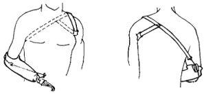
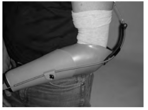
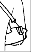
This harness is designed to relieve pressure from the contralateral axilla and to distribute the vertical load from the prosthesis over the ipsilateral shoulder. The control attachment and elbow lock control straps run along the same paths as they do in the standard harness. However, there less contralateral protraction excursion is captured.
The shoulder saddle/chest strap body harness can provide one or two functions: 1) It suspends the prosthesis, especially vertical loads and 2) It provides a reaction point for control operation of cable-operated components.
Component Parts
- Chest Strap
- Stabilizes (anchors) the shoulder saddle.
- Control attachment strap
- Captures motion through the soft tissue – direct pull on the cable for control operation.
- Originates at the cross point, passes over the distal 1/3 of the scapula to the metal hanger on the control cable, then looped back through a 4-bar buckle for adjustability (largest space goes toward the hanger)
- Hanger should not be on scapula.
- Anterior Support Strap
- Prevents distal migration.
- Attaches to the “D” rings at the anterior proximal portion of the triceps pad in the form of an inverted “Y”
- Shoulder saddle
- Carries the vertical loads from the socket
- Lateral/medial loop suspensors
- Location of the medial/lateral suspensors vary on the length of the lever arm.
- Stabilizes and transmits force to shoulder saddle.
- (May not need the medial loop suspensor)
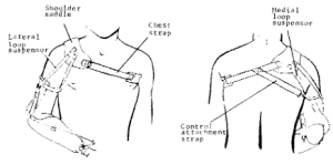
Shoulder Saddle and Chest Strap Harness Assembly
- Obtain 6–8-ounce strap leather lined with horsehide
- Cut 1 1/2” webbing for chest strap, attached with buckle to anterior medial corner
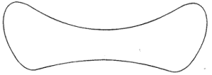
- Add padding under sound side axilla
- Place the shoulder saddle on the amputee, clamp the chest strap to it and adjust for comfort and stability.
- Sew D-rings to the lateral and medial sides of the cuff, at mid-humerus level.
- Attach the medial suspensors (1/2” webbing or leather) to buckles in the front and sew or rivet to the posterior section.
- Control attachment strap: attach 1” webbing to the chest strap slightly towards the sound side of spinal column, but not beyond border of the scapula.
- Align with control cable and fasten to the hanger
- Apply an axial load and observe movement of the shoulder saddle:
- If it buckles above the acromion, the lateral suspensor attachment points should be moved higher on the saddle
- If it buckles medially, the attachment points of the medial suspensor should be moved down on the saddle.
- Completion
- Remove the harness from the patient and sew or rivet where appropriate
- Have the patient don the finished prosthesis and evaluate the fit/function.
Bilateral Transradial Harness
To form this harness, the prosthetist passes the webbing from one inverted-Y suspensor, up over the patient’s shoulder, and diagonally down the back to the control cable of the opposite prosthesis. Repeat the procedure on the other side. The two control attachment straps cross slightly below the seventh cervical vertebra.
Component Parts
- Control attachment strap
- Originates at the cross point, passes over the distal 1/3 of the scapula to the metal hanger on the control cable, then looped back through a 4-bar buckle for adjustability (largest space goes toward the ring)
- Direct pull on the cable for control operation
- Hanger should not be on scapula
- Anterior Support Strap
- Prevents distal migration
- Originates at the cross point, passes over the affected shoulder and the deltopectoral groove
- Attaches to the buckles at the anterior proximal portion of the triceps pad in the form of an inverted “Y”
- Humeral component
- Force transmission to the harness from the socket with a flexible triceps pad
- Force transmission to the harness from the humeral cuff if full cuff
- Location of the crossbar assembly varies on the length of the lever arm and arc of cable travel
- Prevents cable from hitting arm and transmits force
- Crosspoint
- Optimal position is about 1” below C7 and 1” toward the contralateral side on the back
- Crossback strap
- Placed between the control attachment straps of the bilateral harness or the axilla loop and the control attachment strap of a unilateral harness system
- Often necessary to prevent the harness from rising up the back to increase efficiency of the harness to capture excursion
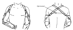
- Images from the UCLA manual, Prosthetic Checkout Chapter 11, William R. Santschi, Lester Carlyle and Norman Berger ↵
