
2 Bridging the Tech Divide: Incorporating Finish Trades into BIM by Redefining the #Hatch-Mark
Hatch-for-Clash
Monica Dawson
Introduction:
To complete the integration of technology into the construction industry, it is finally time to focus on the finish trades. For the past half-century, the construction industry has been infamously slow to adopt emerging technologies[1]. It is only recently that key trades like Mechanical, Electrical, and Plumbing (MEP) have embraced new Building Information Modeling (BIM) processes. These MEP trades create federated models of their various systems to compare and collaborate constructability in the BIM cloud. However, the slow rate of BIM adoption and implementation for specialty contractors and finish trades has limited the efficiency of project communications[2].
Providing a digital platform for specialized trades to communicate both detailed schematic and schedule needs is integral to a successful project. For example, a tile floor in a bathroom could have a specification for heated elements that would require electric components to be installed prior to the tile. In this instance, the finish trade becomes an integral part of the entire building system. Incorporating these details into a 3D constructability phase, for example, avoids unnecessary and costly rework. As such, an early technological invitation by the project managers to the BIM MEP dialogue becomes indispensable. Therefore, the research question at hand focuses on incorporating the finish trades into that dialogue. How can we improve upon existing finish trades models and systems to increase communication and prevent field rework?
Definitions:
Finishes:
What is meant by “finishes” in the industry? The Construction Specification Institute (CSI) MasterFormat categorizes finishes under Division 09[3]. This division defines finishes as floor and wall coverings, finish carpentry, paints and coatings, and so on and lists them under their own subcategories. A good way of envisioning the trades listed under Division 09 is by picturing yourself walking into a building. The immediate impact of finish work is first felt upon entering and can guide an aesthetic vision. Is the building traditional or modern? Luxurious or Rustic? Finish materials combine both form and functionFinish materials combine both form and function. Finish cabinetry, for example, can store items while defining a room’s aesthetic through styled door panels. Why, then, are they most commonly represented in schematic drawings only as “form”?
Division 09 deals with finished materials but there is an often unacknowledged relationship between other CSI divisions in constructability reviews. One such example is the relationship between concrete subflooring (CSI Division 03) and tile floor installations (CSI Division 09). In this example, the two trades are intimately linked and designing one has a parametric influence on designing the other. The finish trade becomes an integral part of schematic design. If we ignore this division, how do we prevent field rework? Specifications like floor flatness, waterproofing, reinforcement, and mortar thickness all have an impact on the overall design of a finished building[4]. Widespread adoption and integration of BIM by both the finish trades and project management would improve project efficiency, communication, and overall success. But in order to do that, a fundamental shift in how the finishes are represented in BIM must change. We argue that the very representation of the finish trades on schematic schematic drawings is outdated and must first be updated to align with the overall goal of the research question.
Therefore, the first step in improving the finish BIM models is to improve upon how they are envisioned within that model. First, we research the past and current uses of finish trade representation in schematic drawings. We can then use that research to create a case study scope in which to analyze a future vision of that representation. This scope will serve as our roadmap for analyzing the potential incorporation of finish trades into future early BIM worklflows.
Hatch-Mark:
Firstly, let’s examine how Division 09 is represented in construction drawings. In order to do so, one should start with a definition of the Hatch-Mark: SYMBOLIC, GRAPHIC, GEOMETRICdivision’s symbology most used in architectural drawings- the hatch-mark. Hatch-marks have three uses: symbolic, graphic, and geometric[5]. The hatch-mark can be symbolic, representing a bush in a landscaping drawing. It can be graphic, such as a shingled rooftop coming to life in a 3D rendering. It can also be geometric, illustrated as intersecting lines meant to represent brick joints on an exterior wall. In order to incorporate these three different uses of the hatch-mark into a BIM dialogue, they all need to be first well defined.
Symbolic:

To further explore these three different uses, we shall travel through time and follow the hatch-mark’s journey through history. Hatch-marks have been used to aid in architectural design and building plan communication for thousands of years. One of these first hatch-mark examples can be found in Egypt circa 1550 BCE depicting a set of plans for a structure[6]. Interestingly, this small shrine drawing and garden plan features W-shaped hatching to depict water and also features other symbols showing landscape features. These hatch-marks served as visual cues, aiding the observer in understanding the intended spatial relationships and features within the design. We know this temple is built along water and features a garden thanks to the ancient hatch-marks. This example from history helps us define the first role of the hatch-mark as that of the symbol[7]. They are ancient integral symbols in architectural drawings, conveying lots of information with simple designs.
Graphic:
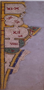
The Roman era builders literally cemented the hatch-mark notation into their architectural drawings by recreating them in stone mosaic form[8]. For example, a mosaic dating from the 2nd or 3rd century BCE depicts elaborate Roman style bath plans with apses and segmental walls[9]. This mosaic consists of three fragments showing different parts of bath buildings, the leftmost one is featured here. The various rooms depict dimensions in Roman Numerals that a master builder might use to construct the building. Of note, we can also see that the finish details of the interior are symbolized via different colors and hatch-marks. The location of the basins and pools are marked by green tesserae, for example, which outline the extent of the wet areas. Compare this color to the darker blue tesserae marking a water channel along an outer corridor, and we can get a sense of an ancient 2D drawing coming to life through colored stones. These stones are, in a sense, 3D hatch-mark blocks. This added incorporation of different colors into architectural drawings allows for a descriptive representation of spaces within a building. Moreover, the use of colors enhances the aesthetic appeal of architectural drawings, making them more engaging and captivating. This mosaic, for example, was installed by a craftsman as a piece of permanent art to be enjoyed. The intricate mosaic patterns and vibrant colors transform what could have been a simple depiction of architectural plans into an elaborate and visually striking rendering. Here is where the idea of the hatch-mark as a visually graphic representation of the building process truly begins to form.
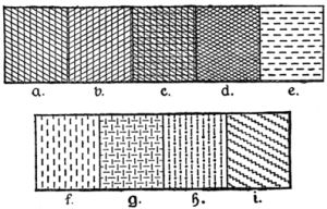
Using symbolic and graphic hatch-marks for plan readability was formalized in the 17th century’s Renaissance era[10]. This period is famous for celebrating artistry, and newly planned buildings and blueprints were painted in gorgeous oil landscapes. At this time, the first so-called “Hatch-System” was created. The importance of this system was to standardize the reproduction of heraldry colors and materials in coats of arms. Hatch-marks were used to depict specific colors and materials that could then be read by trade professionals and later reproduced. The illustrated figure to the right shows one of these examples[11]. Each hatch-mark depicts a different color, for example B was blood-red, G gray, and H was orange. It also depicted materials. C was an earth-color; D was the metal iron; and E water and I nature. The trade professional would use this hatch-mark reference system as key to reproduce flags, shields, paintings, etc. This idea of the hatch-mark as an official symbol can still be seen in use today. The ancient heraldic hatch-mark symbol used to depict the metal gold, for example, is the exact same hatch-mark used in AutoCAD architectural drawings today[12].
In the 1850s, blueprints were invented and used for quickly replicating architectural drawings[13]. Now easily copied, hatch-marks were no longer meticulously hand drawn over and over. A few decades later in the 1920s, the first Architectural Graphic Standards book was published and officially categorized the hatch-marks[14]. This categorization regulated the line widths, spacing, and shapes of commonly used hatch-marks. It also established a difference between hatch-marks for common symbols and illustrative graphic shading, as well as hatch-marks used for different materials.
It is this second definition that is of interest to the builder, as it is the materialized hatch-mark that represents an installation on the job site. It also serves as a perfect example of how the construction industry started to evolve from a master-builder that drew the 2D designs while knowing the 3D impacts, to a group of architects and engineers drawing for separately contracted builders. The very idea of the hatch-mark started to be defined wholly as design, forgetting the inherent installation behind the symbol. Construction designs need to communicate tangible and measured ideas, not just intent and symbols. The third and final definition of hatch-marks as geometric then comes into consideration.
Geometric:
When used in geometry, hatch-marks are used to mark points on an axis and along lines[15]. Hatch-marks are used to “denote equal-measures of arcs, line segments, or other elements”[16]. This ancient geometric principle is important because in 1982, AutoCAD used these basic mathematical definitions to digitize the hatch-mark with its technological drafting software[17]. Under this new age of the architectural drawing, the congruent and parametric value of the hatch-mark comes into play. For example, AutoCAD defines the hatch-mark as a file pattern in a simple x/y graphed format. These hatch-marks are defined geographically on an axis as the “angle, x-origin, y-origin, delta-x, delta-y, etc”[18]. In this role, the hatch-mark as a symbol becomes mathematically represented. Hatch-marks can represent objects arrayed in situ, representing the size and location of certain finishes. Early examples of this hatching system depicts finishes as x and y lines on a screen. We as an Industry have not fully moved on from this idea.
Although the previously carefully hand drawn symbols and lines were now in digital form, the underlying concepts of the hatch-mark were still in the traditional 2D format. Most current technology arrays hatch-marks with a simple click of a button and have no real 3D representation of the installed object. The hatch in this case is still just a symbol, it is merely lines on a virtual wall with no true corresponding 3D modeling or installation notes.
Current Problem:
The arrival of 3D construction management software like Revit and NavisWorks signaled an architectural drawing and communication shift towards BIM. The idea behind BIM technology comes from object oriented parametric modeling techniques[19]. With BIM, a designer incorporates all the building’s components into a single model. That model can then be utilized to produce floor plans, sections, and elevations. When used in geometry, hatch-marks are used to “denote equal-measures of arcs, line segments, or other elements”[20]. Under this definition, the congruent and parametric value of the hatch-mark comes into play. This is where one can see basic geometric principles working, both of which serve as fundamental design principles in 3D construction design[21]. The problem, however, lies within this technical translation of the hatch-mark. BIM software inherited its “computational geometric representation from CAD”[22]. This inheritance maintains the status-quo of hatch-mark as symbolic and graphic, only hinting at the geometric and therefore parametric definitions.
The very idea of the hatch-mark has evolved from ancient symbolic 2D representation to 20th century drafting standards and then morphed into today’s 21st-century 3D depictions. This archival and document review answers our question about WHY the finish trades have lagged behind in BIM. The end user of the hatch-mark has changed while the hatch-mark itself is inherited from a long and ancient line of builders. This brings us to the heart of our case study question, HOW can we improve upon existing finish trades models?
Data Collected:
The case study interviewed industry professionals to define the criteria for a “perfect” hatch-mark. It was at first difficult to track down individuals with intimate knowledge of both installation methods and technology driven modeling. To begin with, basic functionality of the hatch-mark across different software is not standardized. For example, AutoDesk has its own commands for “arraying” hatch marks in Revit versus AutoCAD[23]. Moreover, only a few of the currently available softwares are able to even incorporate a parametric 3D design for finishes. The need for these 3D finish parametric designs is so great it has spawned whole industries to fill those needs. Grasshopper, for example, is a popular app for Rhino and is filled with end-user created 3D finishes[24].
Another great example is SketchUp, a popular 3D modeling program[25]. More hatch systems and pattern options are available for download by both SketchUp and third parties. This program used to have a “3D warehouse” with add-on finish features and user created hatch-mark apps. It became such a popular marketplace of ideas that it is in the process of moderating the apps and creating a subscription based structure to access. These different material and finish software add-ons are independently published by suppliers, architects, design firms and others can be for free, for sale, or for subscription. In a sense, this market is like the old Wild West. The software developers as an industry have not evenly incorporated the technological features into BIM[26]. An owner or project manager searching for a particular finish finds a hatch-mark marketplace with no true regulations or standards. Suppliers publish their products in these 3D model platforms in the hopes the designers use their hatched-marked models and then eventually install the actual product. At this level, design becomes dictated by the suppliers, not the stakeholders. For example, material manufacturers are posting 3D models online via SketchUp’s warehouse (a cloud database for popular construction models) and other modeling systems. A designer can finish out the 3D details of a room with a Grohe brand wide-spread kitchen faucet with hot and cold taps connecting beautifully to a single-holed Kohler branded under-mount sink. These are beautifully depicted models that easily fit into virtual renderings but could schematically cause installation problems. It is up to the individual modeler to then have the ability and knowledge to catch that type of incompatibility as they work in BIM. There is no real established workflow for the finishes, even in current 3D design. Following this trail of thought, our research delved deeper into the SketchUp 3D modeling software in order to identify missing gaps and create a virtual space for the finish trades. How do we reconnect the finished trade to the model, and how do we connect the modeler to the finished trade?
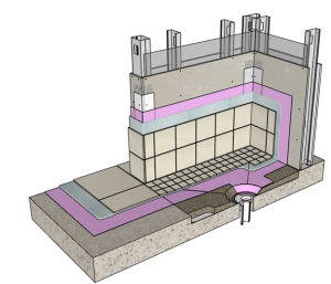
One model stood out against all the others and was used as a basis for the interviews. The International Masonry Institute’s (IMI) Detail Systems translates the entire hatch-mark installation system into a BIM dialogue[27]. This model best fits our definition of a 3D hatch-mark in a few ways. Firstly, this model was created with the intent to educate and to help the end-user visualize the installation materials processes that go into masonry installation[28]. This is important because while currently free, SketchUp has plans to move it’s open source 3D Warehouse into a subscription based plan. Having a model verified by industry experts and meant to educate rather than make a profit ensures an equitable and accurate model. Remember our earlier contention with design becoming dictated by profit, not use. Next, this model incorporates all three definitions of the hatch-mark. It is a complete system that can represent a finish trade in the BIM dialogue. Of most interest is the incorporation of the 3D tile installation information, like expansion joints and shower slope. IMI’s idea for the 3D model first emerged in 2008 with the masonry detailing series. This series focused on brick and concrete masonry units and their installation details[29]. The natural transition into the 3D tile and marble finishing series takes the technical detail specifications of the masonry models and applies them to the finishes. Here we can finally see the hatch-mark defined in 3D on par with industry standards. Finally, the model was created in a software popular with designers and thereby increasing its chances of being used in an early BIM dialogue. This detailing series is still fairly new, however, and IMI is still working on incorporating their SketchUp Series into Hive[30]. Apache Hive is a data warehouse software that can both store and translate the systems between multiple Architectural softwares[31].
Interview Analysis:
Because our IMI tile model series is still rather new to SketchUp (2022) and the importing capabilities to other software is still in development, the case study of the hatch-mark required an additional qualitative research method. This method sought data via industry interviews of the IMI model authors. The two IMI interviewees were recruited via email and involved architect designer Cole Cabler and Director of Industry Development Scott Conwell. The questions asked about their experience in the construction industry to gauge their background and workflow approaches to building- whether it is more technical via computer or field. Next, we asked about the interviewees experience with BIM and software preferences as well as methods. This question served as our roadmap for analyzing the potential incorporation of finish trades into future early BIM workflows. The methodology behind the detail series aligned with our previous archival hatch-mark research. A 2D drawing is limiting in finish constructability and clash detection processes. The questions were then framed in an open-ended manner, asking for experiences and real-life scenarios of these different systems. This last scope of interview questions intended to gather information regarding the “end user” of the detailed finish models.
The interviews gave us a further understanding of developer experiences regarding the existing model’s usability and practicality in representing constructability for finish trades. The purpose of these interviews was to gather descriptive data on modeler’s interactions with finish trades and their suggestions for improvement. HOW can we improve the 3D representation of the finish trades? The results of the interviews were codified to give us a criteria for hatch-mark analysis.
At first the interviews voiced the same problems with the 3D hatch-mark that we encountered in our archival analysis. For example, one architect lamented a “lack of good detailing in the interior world” and noted that most details are called out in the specifications instead of in the drawings[32]. This gap between specification and visualization undermines the clarity and comprehensiveness of the construction documentation. Another revealed his troubled experiences with hatch-marks in a tile assembly. A 2D drawing of a tile install would show “four to five lines drawn close together and is not graphically communicative”. This observation underscores the deficiency in construction drawings and highlights the need for a better representation method.
Bridging the Tech Divide:
Hatch-for-Clash:
By combining years of experience both in the field and working with construction software, the design professionals had further insights into the hatch-mark as gleaned from our archival research. For example, they both highlighted a need for an “online library” and “standardization” across the industry. This call for standardization reminds me of the heraldic systems from the medieval eras and then on to the blue-print standardizations of the 20th century. We see this same call for organization now that we are in the virtual 3D era. Organizing the finish trades in an online arena streamlines the design process and facilitates collaboration among stakeholders. Furthermore, the emphasis on consistency within the finish industry addresses the fragmented nature of current practices. These interviews gave us a bonafide criteria of hatch-marks not just within the superficial framework of an aesthetically appealing 3D rendering, nor the uncommunicative world of 2D drawings, but grounded in decades of experience and knowledge. Hatch-Mark as Form and Function. How, then, do we incorporate hatch-marks into BIM? By defining the finishes in terms of installation and incorporating them into pre-design meetings. By bridging this tech divide, 2D hatch-mark details become possible to translate into 3D feasibility and constructability reviews.
Limitations:
While this study has looked into the challenges in incorporating finish trades into BIM workflows, it is important to acknowledge certain limitations and gaps that warrant further exploration. Firstly, the sample size of industry professionals interviewed was relatively small. There may be variations in BIM adoption and practices across different regions, sectors, and project types that were not fully captured. Next, efforts were made to contextualize the findings within the historical evolution of hatch-mark usage. However, this was a limited historical review merely scratching the surface. A deeper analysis of software variations in BIM adoption could provide additional insights into the challenges faced by different stakeholders. Addressing these limitations through further research would help advance the integration of finish trades into BIM workflows.
Future Theory:
In summary, this case study sheds light on the traditional representation versus current industry practices of finish trades. By tracing the historical evolution of hatch-mark usage and incorporating insights from industry professionals, we have identified a criterion to enhance the 3D representation of finish trades. By redefining the model itself, we can improve communication and prevent field rework. While there are still gaps to be addressed and opportunities for further research, the findings of this case study provide a foundation for future efforts to integrate hatch-marks into the BIM dialogue. By fostering digital collaboration with ALL trades, we can pave the way for more efficient, sustainable, and successful construction projects in the future.
Media Attributions
- “Architectural Drawing of a Garden” The Met Fifth Avenue: Gallery 117 is licensed under a CC BY (Attribution) license
- “Polychrome Mosaic with Building Plan” Copyright Roma, Sovrintendenza Capitolina ai Beni Culturali. is licensed under a CC BY (Attribution) license
- “A Complete Guide To Heraldry” Charles Fox-Davies The Project Gutenberg is licensed under a CC BY (Attribution) license
- 3D Tile Install, IMI Detailing Series
- NAIOP Research Foundation- Mccoy, Andrew PhD, Yeganeh, Armin PhD ↵
- Mohammed, H. S., & Hilal, M. A. (2024). Improving building information modeling (Bim) implementation throughout the construction industry. Journal of Engineering, 30(02), 85–104. https://doi.org/10.31026/j.eng.2024.02.06 ↵
- Tile Council of North America TCNA Handbook for Ceramic, Glass, and Stone Tile Installation 2023 60th ed. ↵
- Tile Council of North America TCNA Handbook for Ceramic, Glass, and Stone Tile Installation 2023 60th ed. ↵
- MathBitsNotebook Basic Geometric Symbols and Labeling n/a MathBitsNotebook (Geo – CCSS Math) ↵
- The Met Architectural Drawing of a Garden: From Egypt, Upper Egypt, Thebes New Kingdom https://www.metmuseum.org/art/collection/search/544801 ↵
- Dodds, G. Drawing Architectural History 2013 Lecture at Appleton Tower, University of Edinburgh ↵
- MacDonald, William L. The Architect: Chapters in the History of the Profession; Ch. 2 Roman Architects 1977 https://books.google.com/books?id=NaYwDwAAQBAJ&pg=PA35&source=gbs_selected_pages&cad=1#v=onepage&q&f=false ↵
- "Polychrome Mosaic with Building Plan" Copyright Roma, Sovrintendenza Capitolina ai Beni Culturali. https://csca.aha.cam.ac.uk/konogan-beaufay-on-roman-mosaics-for-drawing-matter ↵
- Overstreet, K. Which Came First, the Drawing or the Building? Understanding the World's First Architectural Processes 2020 ArchDaily. https://doi.org/ISSN 0719-8884 ↵
- Fox-Davies, A. C. (n.d.). A complete guide to heraldry. Https://Www.Gutenberg.Org/Files/41617/41617-h/41617-h.Htm. Retrieved May 28, 2024, from https://www.gutenberg.org/ebooks/41617/pg41617-images.html ↵
- Autodesk Hatch Pattern Definitions 2023 AutoDesk AutoCAD 2023. https://help.autodesk.com/view/OARX/2023/ENU/?guid=GUID-A6F2E6FF-1717-44B6-A476-0CA817ADD77E Brooke, John SUS: A quick and dirty usability scale 1995 Usability Eval. Ind., Vl. 189 Construction Standards Institute (CSI) MasterFormat. 12th ed. 2024 https://www.csiresources.org/standards/masterformat Conwell, Scott "IMI Detailing Series." 2024 Tech interview at Online Platform, March 7, 2024 ↵
- Oke, A.E., & Stephen, S.S. Digital Technologies for Sustainable Infrastructure Management 2024 Overstreet, K. Which Came First, the Drawing or the Building? Understanding the World's First Architectural Processes 2020 ↵
- The American Institute of Architects Architectural Graphic Standards 2017 Edited by K.E. Hedges. (12th ed.). Hoboken, New Jersey: John Wiley & Sons, Inc. https://doi.org/ISBN 978-1-119-31251-2 ↵
- Heiberg, J.L "Euclid's Elements of Geometry" 2008 https://farside.ph.utexas.edu/Books/Euclid/Elements.pdf ↵
- MathBitsNotebook Basic Geometric Symbols and Labeling n/a MathBitsNotebook (Geo – CCSS Math) ↵
- Autodesk Hatch Pattern Definitions 2023 AutoDesk AutoCAD 2023. https://help.autodesk.com/view/OARX/2023/ENU/?guid=GUID-A6F2E6FF-1717-44B6-A476-0CA817ADD77E ↵
- Autodesk Hatch Pattern Definitions 2023 AutoDesk AutoCAD 2023. https://help.autodesk.com/view/OARX/2023/ENU/?guid=GUID-A6F2E6FF-1717-44B6-A476-0CA817ADD77E ↵
- Lévy, François BIM in Small-Scale Sustainable Design 2011 ProQuest Ebook Central ↵
- MathBitsNotebook Basic Geometric Symbols and Labeling n/a MathBitsNotebook (Geo – CCSS Math) ↵
- Lévy, François BIM in Small-Scale Sustainable Design 2011 ProQuest Ebook Central ↵
- Dossick, C. S., Anderson, A., Azari, R., Iorio, J., Neff, G., & Taylor, J. E. (2015). Messy talk in virtual teams: Achieving knowledge synthesis through shared visualizations. Journal of Management in Engineering, 31(1), A4014003. https://doi.org/10.1061/(ASCE)ME.1943-5479.0000301 ↵
- Autodesk Hatch Pattern Definitions 2023 AutoDesk AutoCAD 2023. https://help.autodesk.com/view/OARX/2023/ENU/?guid=GUID-A6F2E6FF-1717-44B6-A476-0CA817ADD77E ↵
- Associates, R. M. &. (n.d.). Rhino—Search results. Www.Rhino3d.Com. Retrieved May 28, 2024, from https://www.rhino3d.com/searchresults/ ↵
- Trimble Inc. Sketch UP Pro 2023 Version 23.1.340 64-bit 2023 Trimble Inc. ↵
- Abdirad, H., & Dossick, C. S. (2021). BIM technologies, tools, and skills. In BIM Teaching and Learning Handbook (pp. 23–47). Routledge. https://www.taylorfrancis.com/chapters/edit/10.1201/9780367855192-4/bim-technologies-tools-skills-hamid-abdirad-carrie-sturts-dossick ↵
- 3d warehouse. (n.d.). Retrieved May 28, 2024, from https://3dwarehouse.sketchup.com/model/184a2a04c8c00c349d94ba8665682abf/2024 ↵
- Throop, Diane PE, Keith Laashway PE, and Scott Conwell. "Masonry Detailing from Desktop to Job Site." 2008 STRUCTURE Magazine, (2008): 10-13. STRUCTUREmag.org. ↵
- Throop, Diane PE, Keith Laashway PE, and Scott Conwell. "Masonry Detailing from Desktop to Job Site." 2008 STRUCTURE Magazine, (2008): 10-13. STRUCTUREmag.org. ↵
- Conwell, Scott "IMI Detailing Series." 2024 Tech interview at Online Platform, March 7, 2024 ↵
- Hive Hive Cloud Computing hivenet.com ↵
- Cabler, Cole "IMI Detailing Series." 2024 Tech interview at Online Platform, Feb 27, 2024 ↵
